IF to Antenna Transceiver Solution for mmWave Fixed Wireless Access

— 25 to 29 GHz Frequency Coverage
— Solutions for +57 and +63 dBi EIRP
— Supports 400 MHz Channels and 2048-QAM Modulation

mmTron has developed a full IF to antenna solution for 25 to 29 GHz fixed wireless access (FWA) systems, offering two solutions that combine high power (EIRP) and high linearity to enable high data rates for broadband internet access.

The global demand for broadband is fueling the rapid growth of FWA as a cost-effective and easily deployed network for service providers. The mmWave spectrum at 24 GHz and above is increasingly being tapped to ensure sufficient network capacity to provide users with consistently high data rates.

Maximizing the distances between FWA radio nodes requires high power, and maximizing the data rate requires high linearity. The greater the power and linearity, the longer the range and the greater the data rate for the network.

mmTron has developed two transceiver bundles for 25 to 29 GHz FWA systems that support +57 dBi and +63 dBi EIRP transmitters, respectively. These power levels enable operators to extend the reach between radios and reduce the capital cost of the radio access network.

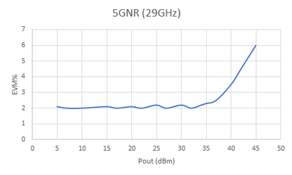
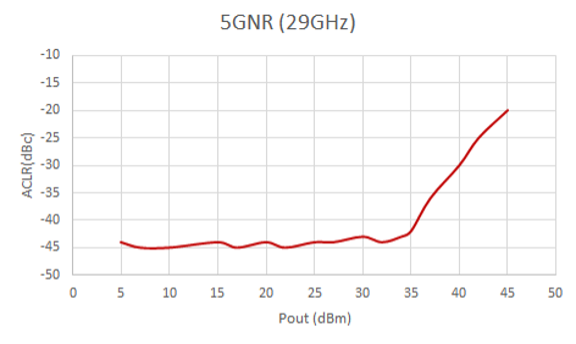
Both transceivers are full duplex that support up to 400 MHz channel bandwidth and 2048-QAM modulation across the full frequency band. A typical dual-polarized FWA radio will use two bundles.

+57 dBi EIRP Solution

The first transceiver solution combines mmTron’s TMC178 and TMC165 in a two-chip bundle (part number TMC178165) to achieve +57 dBi EIRP. Key specs are

— RF Frequency Range: 25–29 GHz
— IF Frequency Range: 5–7 GHz
— LO: 6–8 GHz, 0 dBm Input Drive
— Transmit Output Power: 29 dBm
— Transmit Gain from IF to the Antenna Port: 25 dB
— Built in Transmit Output Power Detector
— Receive Noise Figure: 3.5 dB
— Receive Gain from the Antenna Port to IF: 25 dB
— Only Positive Bias Voltages: +6 and +3 V

The TMC178165 supports full-duplex TDD operation, as the architecture has switches on both the antenna and mixer sides. The switches are controlled with standard control signals.

+63 dBi EIRP Solution

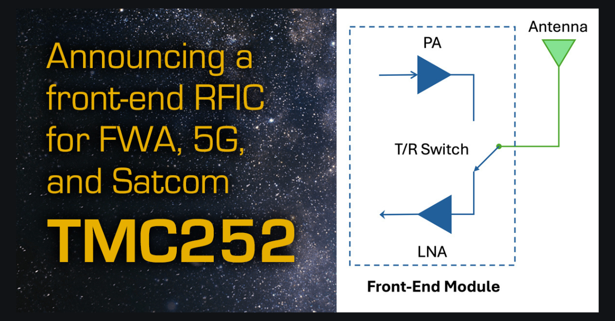
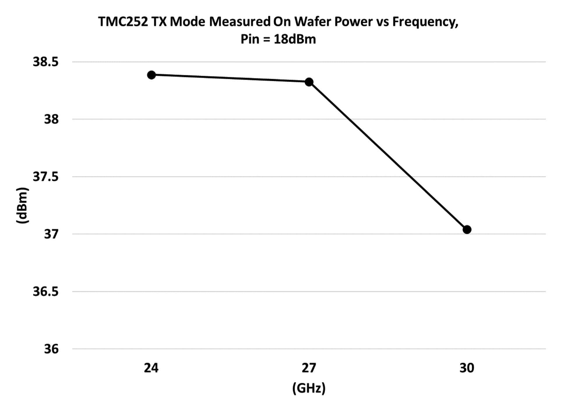
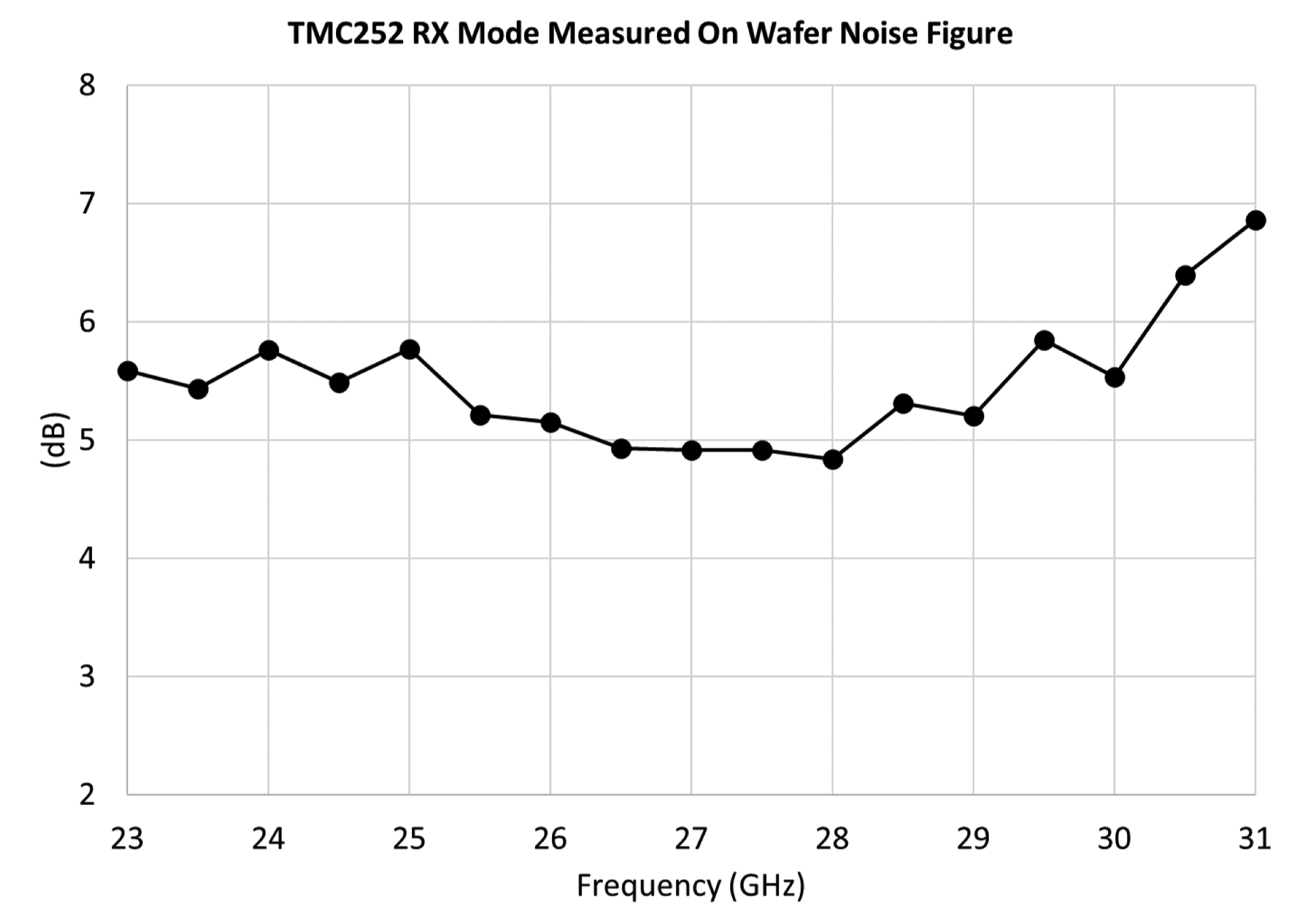
The second transceiver solution combines mmTron’s TMC178, TMC169, and TMC252 in a three-chip bundle (part number TMC178169252) that achieves +63 dBi EIRP. The higher power is achieved by adding a GaN power amplifier, the TMC252. The key specs for the TMC178169252 are

— RF Frequency Range: 25–29 GHz
— IF Frequency Range: 5–7 GHz
— LO: 6–8 GHz, 0 dBm Input Drive
— Transmit Output Power: 37 dBm
— Transmit Gain from IF to the Antenna Port: 25 dB
— Built in Transmit Output Power Detector
— Receive Noise Figure: 3.5 dB
— Receive Gain from the Antenna Port to IF: 25 dB
— Bias Voltages: +23, +6, +3, and –4 V

The specs of the two transceiver solutions are the same except for the higher transmit power of the three-chip solution. The TMC178169252 also supports full-duplex TDD operation, with switches on both the antenna and mixer sides.

The ICs in both solutions are in low-cost, 20-pin, 5 mm x 5 mm, plastic overmold QFN packages.

At IMS2024

mmTron will be discussing these FWA transceivers at the 2024 IEEE MTT-S International Microwave Symposium (IMS) from June 18 to 20 in Washington, D.C. If you’re there, stop by mmTron’s booth, 1661. To schedule a meeting at IMS or request more information and preproduction samples, email contact@mmTron.com.

mmTron’s Disruptive Value Proposition for FWA

Photo of a tower holding multiple radio antennas. Text next to the photo reads Improving the ROI of Fixed Wireless Access

The global demand for broadband access to the internet is fueling rapid growth of fixed wireless access (FWA) and satellite communications, with mmWave spectrum at 24 GHz and above increasingly being tapped to add network capacity.

What is the spec limiting the performance of a mmWave communications system?

Linear power is the key parameter for achieving high data rate mmWave communication. Linearity determines the highest modulation usable for a given channel bandwidth, which sets the maximum data rate of the system. The output power determines the range of a wireless link. The greater the power and linearity, the longer the range and higher data rate for transmission. Power and linearity go hand-in-hand to enable long-reach high data rate systems. High power alone is useless without linearity, because the data rate will not be high enough for demanding internet applications such as high-definition video and emerging VR and AI devices.

mmTron’s power amplifier (PA) products are designed to simultaneously provide high power and linearity while also maintaining excellent efficiency. For example, mmTron’s TMC2111, a GaN PA covering 24.5 to 29 GHz, delivered a record-setting 10 W output power at 3.5% EVM with 30 dBc ACLR, using a 5G NR signal at 29 GHz — to our knowledge the highest linear output power for a MMIC PA at mmWave frequencies.

TMC2111 EVM vs. output power
TMC2111 ACLR vs. output power

Why is the TMC2111’s performance notable?

FCC regulations allow an EIRP of 75 dBm from a FWA base station operating at 28 or 39 GHz. [1] Yet most FWA systems today operate well below that maximum because the EIRP is limited by the output power of the semiconductors and the gain of the antenna array. As the linear output power of a silicon PA is much less than that of GaN — approximately 10x — a silicon-based transmitter requires a larger array than one using GaN to achieve the same EIRP. [1]

Alternatively, the system designer can use an mmTron GaN-based transmitter to increase the EIRP, resulting in a longer distance between antennas. This significantly reduces the number of base stations required and the overall cost of the network, since fewer base stations are needed to cover the same geographical area.

What’s the business case for mmTron?

FWA has emerged as the predominant use for mmWave 5G. Mobile operators are currently tapping unused capacity in their sub-6 GHz (FR1) bands, yet this spectrum won’t support the increasing demand for both FWA and mobile users. Operators must turn to the mmWave (FR2) bands to support this demand.

Ericsson forecasts that global FWA connections will reach 330 million by the end of 2029, up from 130 million at the end of 2023. They forecast the associated data traffic to grow by more than 5x from 2023 to 2029, reaching 159 EB or almost 30% of the total mobile network data traffic. [2]

What’s the take-away?

mmTron has developed a differentiated design and manufacturing expertise for high power, highly linear PAs, as illustrated by the performance achieved by the TMC2111. This unique value proposition is enabling operators to not only reduce the cost of their FWA networks, but also deliver the high data rates users are demanding.

References

[1] “5G Fixed Wireless Access Array and RF Front-End Trade-Offs,” Bror Peterson and David Schnaufer, Microwave Journal, February 2018

[2] “Fixed wireless access outlook,” Ericsson Mobility Report, November 2023, web: www.ericsson.com/en/reports-and-papers/mobility-report/dataforecasts/fwa-outlook

New Product: Single-Chip Front-End Module Covers 24–30 GHz

Block diagram of the TMC252 with the text "Announcing a front-end RFIC for FWA. 5G, and Satcom. TMC252"

mmTron has developed its first single-chip front-end IC for mmWave communications. Covering 24 to 30 GHz, the TMC252 integrates a power amplifier (PA), low noise amplifier (LNA), and transmit-receive (T/R) switch on a single GaN IC that is available as a die or packaged in a 5 mm x 5 mm air-cavity QFN.

The TMC252 is well-suited for fixed wireless access, 5G infrastructure, point-to-point radio, and satellite communications (Satcom). Its broadband performance covers several FR2, radio, and Satcom bands.

Tx Performance

In transmit mode, at 27 GHz the TMC252 provides 38 dBm saturated output power, 37 dBm at 1 dB compression, and 42 dBm OIP3. At saturated output, the power-added efficiency (PAE) is 22%. Small-signal gain is 22 dB. Biased at 23 V on the drain and –3.8 V on the gate, the quiescent current is 590 mA.

TMC252 measured on-wafer output power with 18 dBm drive at 24, 27, and 30 GHz.
TMC252 Tx path measured on-wafer output power with 18 dBm drive at 24, 27, and 30 GHz.

Rx Performance

In receive mode, at 27 GHz the TMC252 provides 19 dB gain with 5 dB noise figure. The output power at 1 dB compression is 25 dBm and OIP3 is 29 dBm. The recommended drain bias is also 23 V, and the current drain is 60 mA with –4.5 V on the gate.

TMC252 receive path measured on-wafer noise figure from 23 to 31 GHz.

T/R Switching

The single pole, double throw GaN switch routes the transmit signal from the PA to a common port, typically connected to an antenna, or the receive signal from the common port to the LNA. It is switched with 0 or 23 V; no negative voltage is required to control the switch.

The TMC252 is available as a die (designated TMC252D) which measures 3 mm x 3 mm x 0.1 mm. It is also available packaged in a 5 mm x 5 mm air-cavity QFN.

The datasheet for the TMC252 may be downloaded here.

PA and Driver for FWA, 5G Infrastructure, and Satcom

To extend the reach of high data rate radios operating in the frequency bands between 24 and 30 GHz, mmTron has developed a linear power amplifier (PA) and companion driver, both fabricated with a high linearity, high reliability GaN process.

TMC254 24–30 GHz PA

Small-signal performance of the TMC254D measured on-wafer.

The TMC254 PA delivers 39 dBm saturated output power with 29.5% power-added efficiency (PAE). P1dB is 38 dBm and OIP3 is 44 dBm. Linear gain is 24 dB.

The 24 to 30 GHz bandwidth of the PA supports high data rate applications like fixed wireless access (FWA), 5G infrastructure, Satcom, and supporting test and measurement systems. The linearity of the PA enables system designers to extend the reach and/or the data rates of their radio links.

The TMC254 is typically biased with 28 V on the drain and –3.8 V on the gate, drawing 588 mA quiescent current.

The PA is available as a die (TMC254D) or packaged in a 5 mm x 5 mm air-cavity QFN (TMC254). The die size is 3.0 mm x 3.0 mm, and the IC’s thickness is 0.1 mm. Bond pad and backside metallization are Au-based to ensure compatibility with wire bonding and high conductivity epoxy or eutectic die attach.

Download the TMC254 data sheet here.

TMC248 22–30 GHz Driver

Small-signal performance of the TMC248D measured on-wafer.

The companion TMC248 driver amplifier covers 22 to 30 GHz and provides 20 dB small-signal gain, 27 dBm saturated output power, 26 dBm output at P1dB, and 30 dBm OIP3.

The output power of the TMC248 is more than sufficient to drive the TMC254 to its saturated output without degrading the linearity of the signal chain. The driver can also be used as the PA in lower power systems.

Like the PA, the driver is typically biased at 23 V on the drain and draws 60 mA quiescent current at –4.5 V gate bias.

Available as die (TMC248D), the size of the IC is 3.0 mm x 3.0 mm, and the IC’s thickness is 0.1 mm. Bond pad and backside metallization are Au-based.

Download the TMC248 data sheet here.